Variant 1: Measurement of 3-D geometries
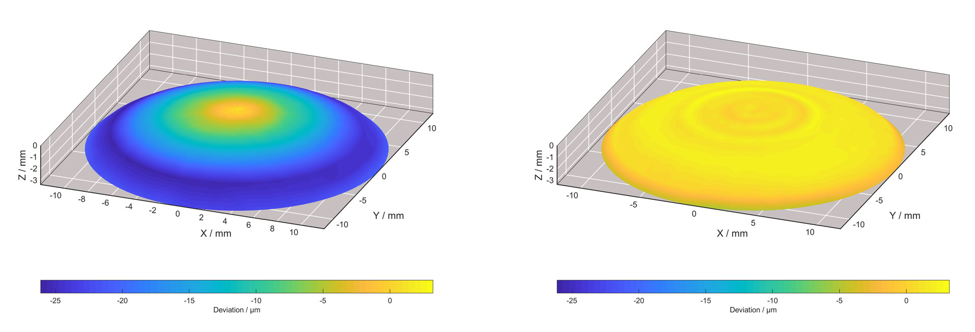
The example of an aspheric lens illustrates the effects of 3D-ToolComp: the left image shows the form errors after the initial test cut, as determined by probing cycle 444. The right image shows the machined lens after compensation of the radius deviations with 3D-ToolComp.
The procedure is as follows:
1. Use the tool to perform a milling operation on a test workpiece.
2. Then measure the resulting contour using a touch probe in combination with Cycle 444 PROBING IN 3-D.
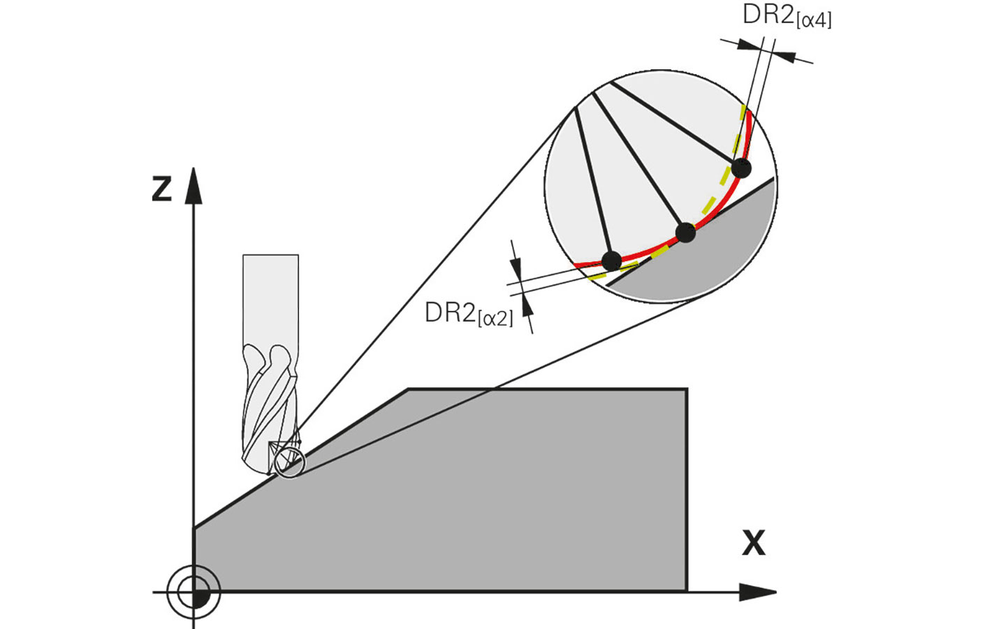
The discrepancies between the milled contour and the desired contour are used to derive the tool radius deviations, which can be entered directly into a compensation table.
Tip: Before probing the workpiece surface, use 3D-ToolComp to perform a 3-D calibration of the touch probe.
Variant 2: Measurement of the tools
You can measure the tool form fully automatically using a laser system and a special cycle, so that the TNC control can directly use these data and record them in a compensation table. After doing so, you no longer need to perform tool compensation in the NC program.
Tip: With this method, the TNC control automatically handles the variable effects of tool form errors and thereby meets an important criterion for reliable machining processes in conformity with medical technology requirements.
Perform highly accurate in-process quality inspection
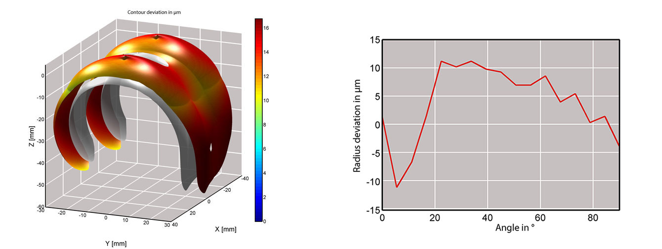
By the way, 3D-ToolComp can do more than compensate for radius deviations on cutters and optimize your machining results. This option also assists you with the high-accuracy quality inspection of workpieces featuring free-form surfaces inside the machine’s work envelope. To receive highly accurate measurement results, use 3D-ToolComp to perform a 3-D calibration of the touch probe before utilizing Cycle 444 PROBING IN 3-D. The cycle then compensates for the distinct switching behavior of the touch probe in any direction.
Cycle 444 is used for the automatic measurement of points on free-form surfaces. To do this, simply enter the given measuring point with its coordinates and the associated normal vector into the cycle.
- After probing, the TNC control automatically determines whether the measured point lies within a defined tolerance.
- Cycle 444 also automatically generates a convenient calibration chart in HTML format.
- In addition, you can request the results via system parameters in order to initiate rework under program control, trigger a program stop, or issue a notification, for example.


